How to read a floor plan like a designer
Most people meet a floor plan as a black-and-white drawing that looks like a map. It is not a map. It is a horizontal slice through a building, taken at about counter height, drawn to a stated scale and annotated with a small vocabulary of line weights, fills and symbols. Nearly every misreading — a wall that turns out to be structural, a sofa that does not fit, a door that opens into a cabinet — comes from treating that slice as a picture instead of a set of conventions. This guide is for the two people who use a plan most: the designer who has to draw it and the client who has to approve it. It covers what the cut shows, what the fills mean and do not mean, which parts are measured and which are only symbolic, and the five things clients misread most often.
HomeDesignly editorial team10 min read
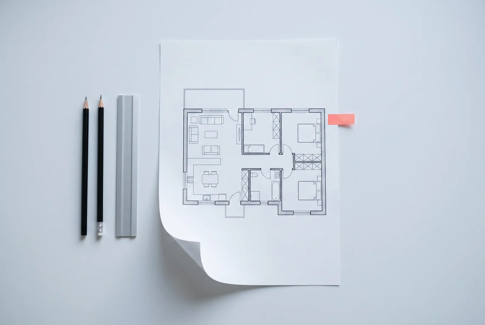
Key takeaways
- A plan is a slice at about counter height, not a view from above: what sits below the cut is drawn thin or left out, and what sits above it is dashed or missing[1].
- Line weight is a reading order, not a material: a 0.50 mm outline and a 0.25 mm note line say which line to look at first, not what the wall is made of[1].
- The fill inside a wall (poché) makes a material claim, not a structural one; whether a wall carries a load is an engineering question, and load-bearing work needs a permit[5, 6].
- A dimension string beats a scaled measurement every time: plans are drawn at 1/4 inch = 1 foot or 1/8 inch = 1 foot, and a printed, scanned or photographed copy is not a measuring instrument[4].
On this page
A plan is a cut, not a view
Think of a horizontal slice through the building at about counter height, seen from above. Everything the slice passes through gets a heavy outline and a fill: walls, columns, the jambs of openings. Everything below the cut — floor finish, a rug, the base of a cabinet — is drawn thin or left out. Everything above it — wall cabinets, a beam, an arch — becomes a hidden line, because it is overhead and would not appear in the slice at all[1].
That one rule explains most of the empty-looking space on a working drawing. Industry drafting standards separate a presentation drawing, which shows furniture and finishes so a client can picture the room, from a working drawing, which leaves the furniture out because the contractor is not building it[1]. So an empty room on a plan is not evidence that nothing fits; it is evidence about who the sheet was drawn for.
Walls, poché and line weight
Line weight is how a drawing tells you what to read first. A heavy line holds the outline of the cut building, a medium line marks a change of plane, a thin line carries notes and dimensions, and hatches are drawn at the lightest weight so several of them close together do not turn into a dark blob[1]. A common teaching set puts the heavy, medium and thin lines at 0.50 mm, 0.35 mm and 0.25 mm[1]. A firm's own standard can use different values, but the order — heaviest at the cut, lightest in the detail — is what makes the sheet legible.
The fill inside a cut wall is called poché. It is where the plan makes its first material claim: a solid fill, a diagonal hatch, a dot pattern, or nothing at all. Hatches are the part of the drawing that separates materials in two dimensions, and a working drawing is expected to hatch at least insulation, plywood, OSB, solid wood, concrete, gravel and earth[1]. Read the hatch before you read the shade of the fill.
What each floor-plan convention means, and what it does not tell you[1]
What is drawn to scale, and what only looks like it
Every sheet carries a scale, usually in the title block in the lower right corner, though it can appear anywhere and can change from sheet to sheet[4]. For buildings, the common architect scales are 1/4 inch = 1 foot (1:48) and 1/8 inch = 1 foot (1:96)[4]. A detail drawn at 3/4 inch = 1 foot is a detail, not a room.
What that means in practice: the geometry is measured, the symbols are not. A door swing, a fixture outline, a stair arrow and a hatch pattern are drawn at whatever size reads clearly, not at the size of the thing they represent. The numbers in the dimension strings are the measurement of record. If a number and the drawn line disagree, the number wins and the sheet needs a revision.
A plan that arrives as a PDF, a screenshot or a phone photo is no longer a measuring instrument: printing, scanning and resizing all change the scale. When a title block says not to scale off the drawing, the drafter is telling you the same thing. Ask for the dimension, or measure on site.
A useful habit before you trust anything on the sheet: pick one dimensioned element you can also see in the room — an opening, a run of wall — and check that the number and the room agree. If they do not, the drawing is out of date, and every other dimension on it needs the same suspicion.
Five things clients misread
- 1. The wall fill. A solid black wall and a hatched wall can both be partitions. The fill names a material; it does not describe a load path[1]. Whether a wall carries anything above it is a structural question, and a licensed engineer is the person who answers it[6]. A client who reads a dark fill as "structural" will sometimes refuse a change that is entirely possible, and a client who reads a hatched fill as "just a partition" can approve a change nobody has checked.
- 2. The apparent size of the room. The rectangle is geometry at scale, but the dimension string is what you build to — and a copied, scanned or resized plan breaks even that[4]. Read the number, not the shape. The same room can look generous on a screen and tight on site once a radiator, a door swing and a wardrobe are in it.
- 3. The door swing as clearance. The arc shows the leaf and which way it opens; it does not show the clear width once the door is open, or whether the swing will hit the vanity. For the required egress door, the code asks for a clear width of at least 32 inches, measured with the door open 90 degrees[3]. Draw the open leaf and the furniture it reaches before you approve a bathroom layout.
- 4. The things that are not drawn. Wall cabinets, beams and arches sit above the cut and appear as dashed lines, or drop off a working drawing that omits furniture by design[1]. An empty wall on the sheet can still be a wall with a cabinet on it, and an empty room on a working drawing is not a room without furniture.
- 5. A revision as a small change. Move one wall and the dimensions, doors and fixtures on that side of the room can all follow. Read the revision marker, then read every sheet it touches before you approve the change. The revision marker tells you where the change starts; it does not tell you where the consequences stop.
What a floor plan cannot decide for you
A plan shows what is there. It does not authorize what you do to it. Four things sit outside the drawing:
Structure. A partition carries only itself; a load-bearing wall carries the floor or roof above it[6]. The two can be drawn with the same line. A structural engineer determines which is which and designs the beam if a wall comes out[6]. In Seattle, any work on load-bearing supports needs a permit no matter how small the project[5]; many jurisdictions are at least that strict. A plan that shows a wall is not permission to remove it.
Stairs. The plan gives you an arrow and the word UP. The code gives the numbers: a maximum riser height of 7 3/4 inches and a minimum tread depth of 10 inches[2]. Those live on sections and details, not on the floor plan.
Openings. The required egress door needs a clear width of at least 32 inches and a clear height of at least 78 inches[3]. A door symbol cannot prove either dimension.
Services and what is overhead. Outlets, plumbing, ducts, joist direction and beam locations belong to other sheets. And a photograph, a sketch or a generated drawing is not a site measurement: measure the room before you order anything from it. The drawing can be right about the room and still wrong about the wall you are about to put a cabinet on.
How to read one in order
Read the same way every time, and the plan stops being a puzzle:
Start with the title block: scale, date and revision[4]. Then the north arrow, because it decides which wall gets the morning light. Then the outline and the poché, exterior walls first, marking every wall you suspect is structural. Then the dimension strings, overall first, then room by room, writing the numbers down rather than trusting the shape. Then the openings: every door swing, every window, and what each swing hits. Finally the sections, elevations and details, which are the sheets that answer height, stairs and structure.
A practical shortcut for the first pass: rebuild the plan you were given in the floor plan creator before you change anything. Redrawing the walls and openings forces you to read every dimension, and the wall that does not close usually shows up within the first ten minutes.
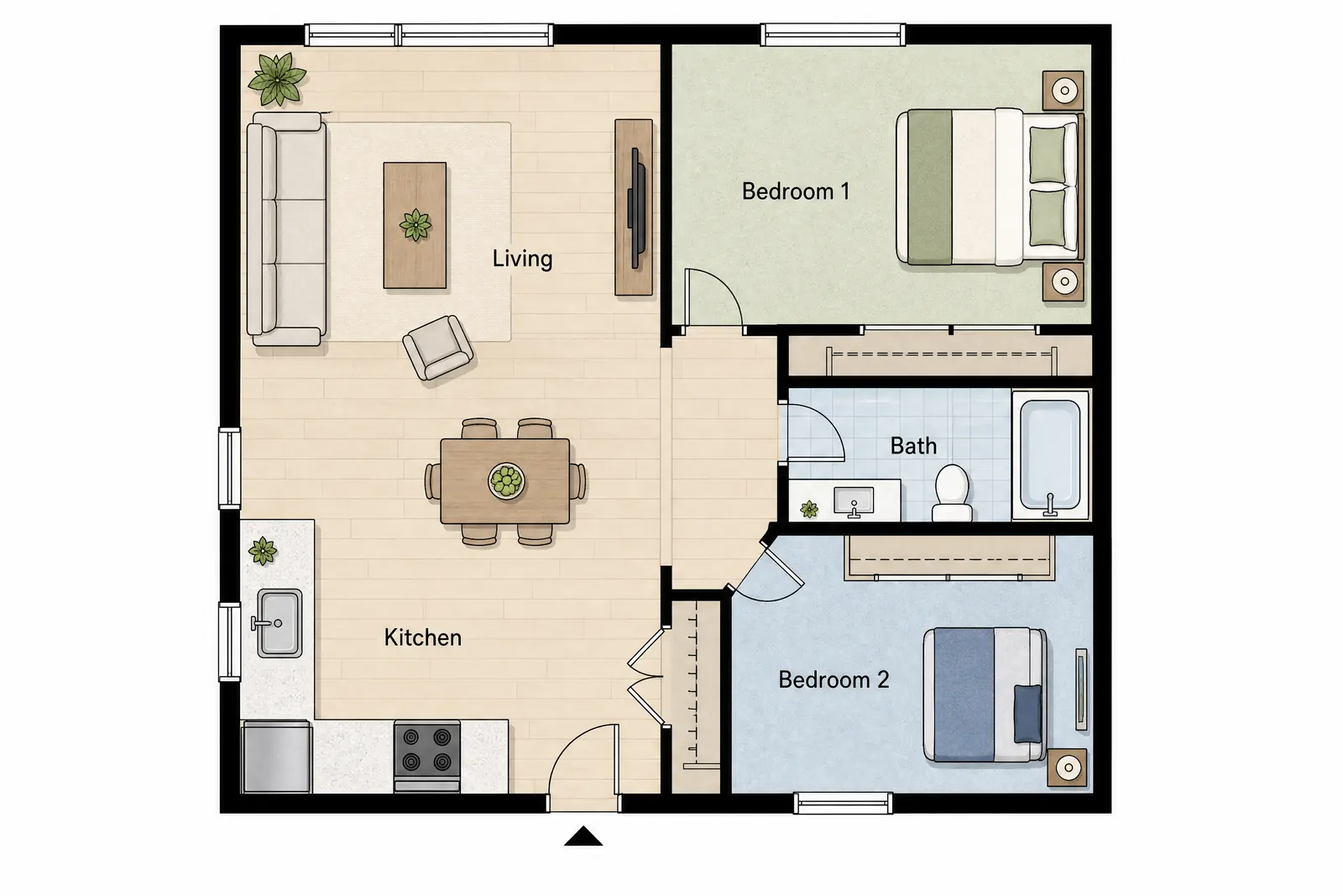
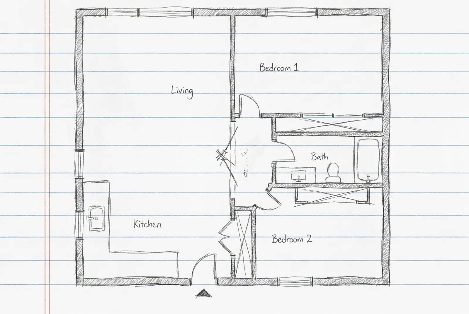
If what you have is a sketch or a list of rooms rather than a drawing, the AI floor plan generator can turn it into a first plan to check, and floor plan to 3D shows the same plan as a model so a client can walk the layout. Both are starting points for a conversation, not a survey.
Turn a sketch into a plan you can check
If what you have is a sketch, a photo or a list of rooms, the floor plan generator turns it into a drawing you can measure and question. Use it while changes are still free, then take the questions to the people who will build it.
Frequently asked questions
What do the different line weights mean on a floor plan?
They set a reading order. A heavy line (often around 0.50 mm) holds the cut outline of the building, a medium line (around 0.35 mm) marks a change of plane or a fixture, and a thin line (around 0.25 mm) carries notes and dimensions, with hatches at the lightest weight[1]. The values vary by office; the hierarchy does not.
Can I tell whether a wall is load-bearing from a floor plan?
Not reliably. A partition and a load-bearing wall can be drawn the same way, and the fill names a material rather than a load path[1]. A structural engineer determines which walls carry load and designs the support if one is removed[6]; work on load-bearing supports needs a permit even when the project is small[5].
Is a floor plan drawn to scale?
Yes, at the scale printed in the title block — commonly 1/4 inch = 1 foot or 1/8 inch = 1 foot for buildings[4]. The geometry is to scale but the symbols are not, and a printed, scanned or photographed copy has lost the scale, so build to the dimension strings, not to a measurement taken off the page.
What does a dashed line mean on a floor plan?
Usually something above the cut plane: a wall cabinet, a beam, an arch or another overhead element that would not be in a slice at counter height[1]. It is drawn dashed so you do not confuse it with a wall you can walk up to.
Sources
Numbers in brackets in the text point to these sources.
- 1.Skills/Compétences Canada, SCNC 2019 – Drawing Standards, 52 – Architectural Technology & Design (Secondary), Appendix 1: Industry Drafting Standards, accessed November 2, 2026.
- 2.City of Boise, IRC Code Handout #437: IRC Section R311.7.5, Stair Treads & Risers, accessed November 2, 2026.
- 3.North Carolina Office of State Fire Marshal, RE: 2018 NC Residential Code Section R311 Means of Egress (formal interpretation, 2023-10-18), accessed November 2, 2026.
- 4.U.S. Fire Administration (FEMA), Using Engineer and Architect Scales, accessed November 2, 2026.
- 5.Seattle Department of Construction & Inspections, Do You Need a Permit?, accessed November 2, 2026.
- 6.Pittsburgh Design & Engineering Services, Is It Worth Paying a Structural Engineer to Determine Load-Bearing Walls?, accessed November 2, 2026.