How to draw a floor plan to scale, and check it before anyone builds
A floor plan goes wrong in one of two places: the measurements, or the scale. Everything else — the furniture, the door swings, the careful furniture layout — is downstream of those two decisions, and both are made before the first line is drawn. This is the working method for a measured plan of an existing room or floor: what to measure on site, how to choose a scale that fits the sheet, the order to draw in, and three checks that catch a drawing that is quietly 10 percent wrong. None of them needs special software; a tape measure, a scale rule and a pencil will do, and the same checks apply to anything drawn in a plan editor.
HomeDesignly 编辑团队阅读约 11 分钟
本文只有英文版。
要点
- A scale is a ratio written two ways: 1/4 inch = 1 foot is 1:48, and 1/8 inch = 1 foot is 1:96[1].
- The scale belongs in the title block, and one set can carry several scales when details are enlarged[1].
- Written dimensions always take precedence over measurements scaled off the drawing[1], and drawings say so: dimensions govern, do not scale[5].
- A print resized to fit the paper is no longer to scale; a graphic scale bar is what survives the resize[1, 4].
- Three checks catch most bad plans: the room's diagonals, the perimeter closing, and a door opening that does not match its tag[1, 5, 6, 7].
本页内容
Measure before you draw
Measure the things you intend to draw, and nothing you do not. For each room: every wall face, corner to corner; every opening, with its width and the side the door hinges on; the wall thickness at one opening, because that is the only place you can see the full depth of the wall; and the clear ceiling height. Note the fixed obstructions — a radiator, a soil pipe, a beam — because they decide where furniture can go later, and they are the things a plan is expected to show.
Measure at floor level, along the finished face, and write the numbers on a paper sketch as you go. Two habits save a return visit: measure the opening rather than the door leaf, since the leaf sits partly inside the frame; and check one dimension twice, at both ends, because a room that is not square will give you two different widths and both of them are true.
This is not fussiness. Construction documents put the same obligation on the builder: they require field measurements of existing conditions before the work is priced or fabricated[5]. A photograph, a phone scan or a plan borrowed from a listing is evidence of a shape, not a measurement, and if a dimension is missing the honest move is to leave a note on the drawing rather than fill it with a guess.
A measurement sketch is not a drawing, and it does not need to be neat: a rectangle per room, the numbers written on the lines they belong to, a circle round every dimension you are not certain of. What it does need is to be complete enough that the drawing can be rebuilt from it alone, months later, without the room in front of you. Anything awkward — a chimney breast, a sloped ceiling, a step between rooms — is drawn as its own small rectangle rather than averaged into the wall.
Choose the scale, and write it down
A drawing scale is a ratio, and it is written two ways. Imperial architectural drawings use 1/4 inch = 1 foot, which is 1:48, or 1/8 inch = 1 foot, which is 1:96; the number after the colon is how many times the real thing has been shrunk[1]. Metric sets use 1:50 or 1:100 for the same job[4]. Either way the scale is a decision about legibility, not about taste: the smaller the ratio, the more the drawing fits on a sheet and the less of it you can see.
The scale normally appears in the title block in the lower right-hand corner of the sheet, and a set may carry more than one when details are drawn larger[1]. When you draw for yourself, decide the scale before the first line and write it beside the drawing, so a reader never has to guess.
The rule of thumb is arithmetic. A 12 foot wall is 6 inches long on paper at 1/2 inch per foot, 3 inches at 1/4 inch per foot and 1.5 inches at 1/8 inch per foot[1] — which is exactly the difference between a drawing on which you can place a vanity and one on which you can only place rooms.
If the drawing does not fit the sheet at the scale you chose, step down to the next standard ratio rather than inventing one in between. An architect's scale carries a fixed set of ratios[1], so a scale that is not on the rule is one the reader cannot check with the tool in their hand.
Draw in the right order
Set the scale first, then draw the wall faces as one closed loop per room — a chain of lines that ends where it started. Openings come next, as gaps in that loop rather than lines drawn on top of it, because a door is a hole in a wall before it is a leaf and an arc. Doors and windows follow, then the fixtures, then the dimension strings outside the outline. Furniture goes last, because it is the only layer you can move without changing the building.
Line weight carries the hierarchy. The drafting standard used in the first post of this series sets three weights, heavy at 0.50 mm, medium at 0.35 mm and thin at 0.25 mm, and puts dimensions and hidden lines at the thin end[2]. So the wall outline is heavier than the fixtures, dimension lines stay hairline and unbroken[2], and a reader can tell at arm's length which lines are the building and which are the annotation.
Dimension strings go outside the plan, one string per wall run, reading the same way throughout the sheet. Where a dimension repeats — a run of identical windows, for example — draw it once and say so, rather than writing the same number five times and inviting a transcription error on the fifth.
One habit keeps a hand-drawn plan honest: dimension each wall run once, from a corner rather than from the middle of the wall, and keep every string on the outside of the outline. Dimensions drawn inside the room collide with furniture, and a number that sits on top of a sofa is a number someone will misread. The same rule holds in software — the layer order is different, the reading is the same.
Three checks that catch a drawing that is 10 percent wrong
A plan can look convincing and be measurably wrong. These three checks find most of it, in this order, because each one is cheaper than the next.
**Diagonals.** Measure both diagonals of every room you have drawn, on paper and in the room. In a true rectangle they are equal; if the two diagonals differ, a corner is not square, and everything placed against that corner inherits the error. At 1/4 inch per foot a 1/16 inch error on paper is 3 inches in the room, and at 1/8 inch per foot the same slip on paper is 6 inches[1] — which is why the check is done on paper before the dimensions are added, not after.
**Perimeter.** Add the wall lengths around each room and compare the total with the sum of the dimensions on site. A room that closes on paper but not on site means one measurement was taken to the wrong face, usually at a doorway where the frame projects past the wall.
**The door.** Compare the drawn opening with the tag and the schedule. A door symbol shows the swing[3]; the door tag is what connects the opening to its schedule row, where the size lives[7]. The required egress door of a dwelling must give a clear width of 32 inches (813 mm) and a clear height of 78 inches (1981 mm), measured with the door open 90 degrees[6], so a drawn opening that cannot give that width is a problem the plan can reveal before anyone orders the door.
When a check fails, the fix is never to nudge the drawing until it looks right. Go back to the measurement sketch: re-add the wall lengths, re-check which face each dimension was taken to, and redraw the room from the numbers. A plan corrected by eye keeps the error and hides it, which is worse than a plan that is visibly unfinished.
What the drawing cannot do
Two limits are worth writing on the sheet itself. First, written dimensions always take precedence over scaled measurements, because reproduction can resize an image to fit the paper and the scale the designer intended is then no longer holds[1]. Second, a drawing is not a substitute for the room: the contract documents used on real projects say dimensions govern and instruct that drawings are not to be scaled, and they require field measurements of existing conditions[5]. Your own plan deserves the same footnote.
That is also why a scale bar belongs on the drawing even when the ratio is written in the title block: a reproduction made to fit another sheet size stays readable against the bar, which is the one part of the drawing that shrinks with everything else[4].
If the only record you have is a photo or a scan, treat it as a starting point and rebuild it at a known scale, then re-measure on site. The floor plan creator opens a template with the scale already set, so a photo can be traced into a measured plan without choosing a ratio from scratch, and the checks above can be run on something that has numbers attached. If you are new to reading the result, start with how to read a floor plan: it covers line weight, what a plan cut shows, and the five things clients misread — this post assumes that vocabulary.
Start from a plan that already has a scale
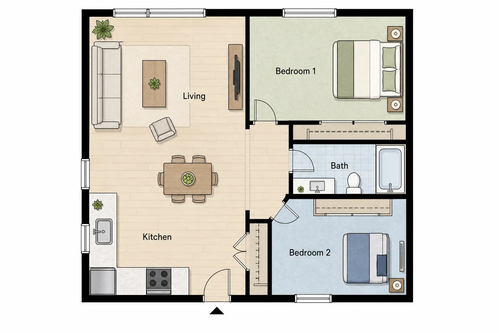
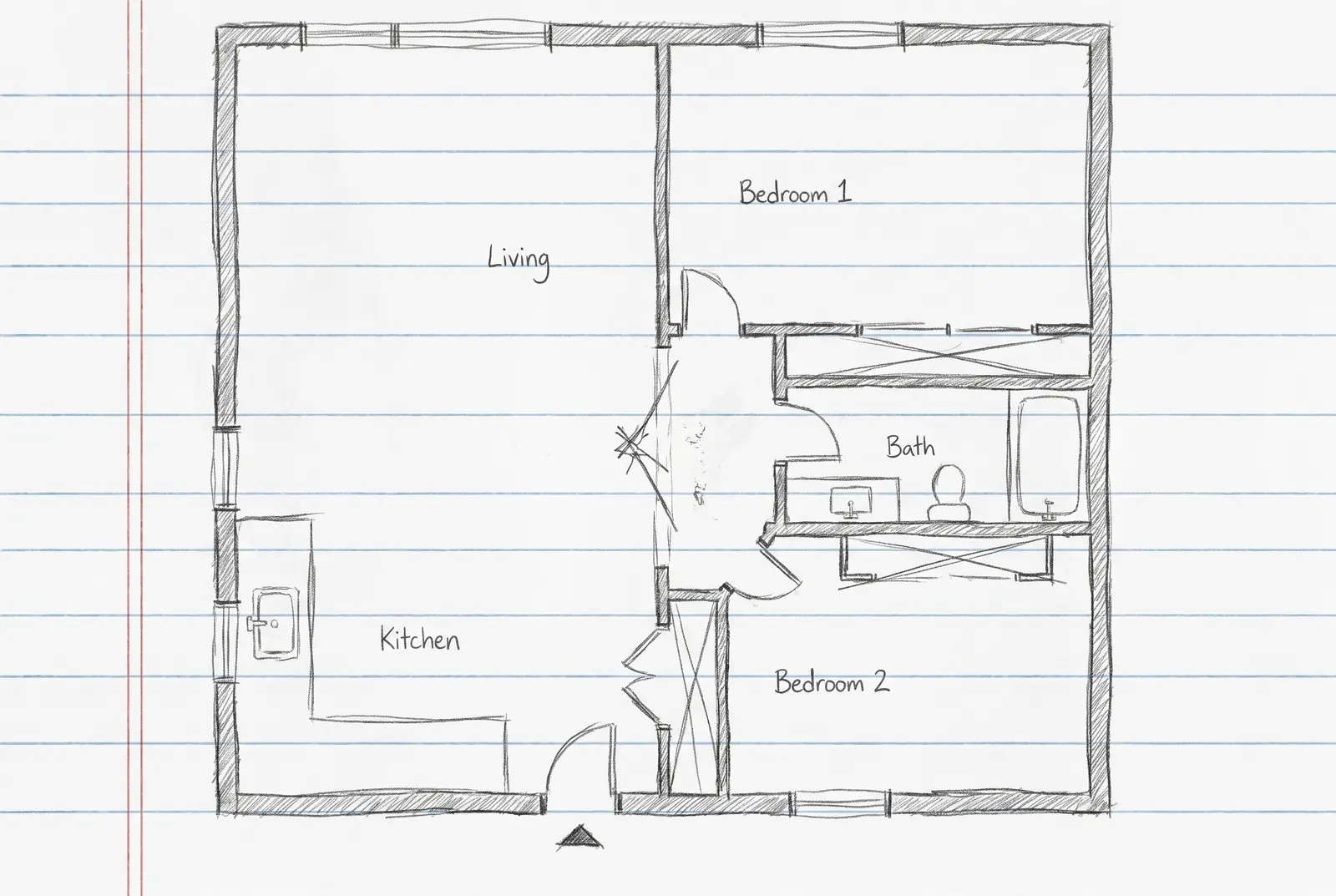
The generator draws walls, openings, stairs and fixtures at a real size, so the checks in this post have something to check: a room that closes, doors that open, and dimensions you can compare with the tape measure you took on site.
常见问题
What scale should I draw a house floor plan at?
For a single room with furniture, 1/4 inch = 1 foot is the working scale; the same room at 1/2 inch = 1 foot is what you use when a vanity or a door swing has to be readable. For a whole floor, 1/8 inch = 1 foot; in metric sets, 1:50 or 1:100 do the same job[1, 4].
Can I measure a distance off a printed plan?
Only if the sheet was printed at actual size. Reproduction can resize an image to fit the paper, and then the printed scale is no longer the designer's scale — which is why the written dimensions always win over anything measured off the drawing[1]. A graphic scale bar is what makes a resized print readable again[4].
How do I check a plan I have just drawn?
Three checks, cheapest first: both diagonals of every room (they should match), the wall lengths summing to the perimeter you measured, and each door opening against its tag and schedule row[1, 7]. And keep the site measurements beside the drawing — the numbers on the drawing take precedence over the drawing itself[1, 5].
来源
正文方括号里的数字对应以下来源。
- 1.U.S. Fire Administration (FEMA), Using Engineer and Architect Scales, 访问于 2026年11月3日.
- 2.Skills/Compétences Canada, SCNC 2019 – Drawing Standards, 52 – Architectural Technology & Design (Secondary), Appendix 1: Industry Drafting Standards, 访问于 2026年11月3日.
- 3.BOMA Oakland/East Bay, Reading Construction Plans – Property Manager Training (symbols and door tags), 访问于 2026年11月3日.
- 4.University of Calgary, Design Standards 8.1: Drawing Standard (measurement units and recommended scales), 访问于 2026年11月3日.
- 5.City of Austin, Building permit plan set, general notes (dimensions govern, field measurements), 访问于 2026年11月3日.
- 6.New York State Department of State, Division of Building Standards and Codes, 2020 Residential Code of New York State, R311.2 Egress door, 访问于 2026年11月3日.
- 7.ArchitectureCourses.org, Architectural Drawing Symbols: Complete Guide for Students and Professionals, 访问于 2026年11月3日.