Floor plan symbols: a working legend for reading any plan
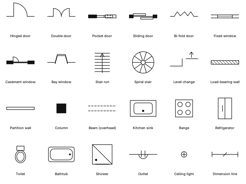
Every floor plan is a small dictionary written in a private dialect. The door with a leaf and an arc is nearly universal; the way the same office draws a pocket door, a bay window or an outlet is not. Designers learn to read the dialect quickly because they read a dozen plans a month, and clients do not, which is why a drawing that looks complete can still be misread by the person paying for it. This page is the vocabulary. Twenty-four symbols are drawn above and described one by one below, then the door family in detail, the wall and structure conventions that are misread most often, and the abbreviations plans actually use. Every row says what the symbol shows, where it turns up, and what it does not tell you — because the last of those is where plans go wrong.
HomeDesignly 编辑团队阅读约 11 分钟
本文只有英文版。
要点
- Symbols are conventions, not one fixed alphabet: the legend on the sheet overrides any chart, including this one[3].
- A hinged door carries two facts in one graphic — the leaf shows the hinge side, the arc shows which room loses the floor[2, 3].
- A filled or heavy wall line is not proof that the wall carries load; line weight is a drawing hierarchy, not a structural finding[3].
- Dashed double lines are things above the cut — a beam, an arch, a wall cabinet — not something standing on the floor[1].
- Size, height, rating and material never live in the symbol; they live in the tag and the schedule the tag points to[3].
本页内容
Read the legend before you read the symbols
A plan is a drawing with a vocabulary, and the vocabulary is local. The same door can be a leaf with an arc in one office and a filled panel with a dashed track in the next; a window can be three lines in one set and a single heavy line in another. What does not change is the reading method: find the legend, read the mark in its context, and follow the tag when the mark is carrying information you actually need[3].
The legend matters more than any chart, including this one. It sits on the cover sheet or the first plan sheet and it defines the symbols, the line types, the abbreviations and the tags that the drafter used. Where a chart and a legend disagree, the legend is what the drawing says[3] — and where the legend is silent, the sheet title and the discipline at the corner of the sheet are the next clue. A wall receptacle is drawn on or against a wall line; a ceiling fixture sits out in the room, usually on a lighting plan or a reflected ceiling plan. Both can be circles[3].
The drawing below is the same idea in one image: twenty-four symbols in the order this page describes them, drawn the way a residential plan usually draws them.
Doors and windows: what the arc and the lines say
A hinged door is two facts in one graphic. The leaf is a straight line standing in the opening; the arc is the floor the leaf sweeps. The end of the leaf that meets the wall is the hinge, and the side the arc bulges into is the room the door opens into — which is also the room that loses that floor[2, 3]. Furniture inside the arc blocks the door, so the swing is read before anything is placed.
The rest of the family is defined by the absence of an arc. A pocket door slides into a slot in the wall[6], a sliding door is offset panels with no swing[6], and a bi-fold folds into a zig-zag at the jamb[3]. None of them needs floor in front of it; each needs an empty wall, a track or a stack depth instead.
Windows are drawn inside the wall thickness, and the plan is the weakest place to learn what a window does: whether it is fixed, casement, awning or sliding may be clearer on the elevation or in the window schedule[3]. The eight rows below are the door and window family, in the order they are drawn above.
Structure, fixtures and annotation
Walls are drawn as two lines for their faces, and walls cut by the plan are usually heavier than objects seen beyond the cut[3]. The fill between the lines is a convention for the cut, and offices use different fills, or none, to say what the wall is made of[1, 3]. That is why a filled wall is not a load-bearing wall: heavy linework belongs to the drawing hierarchy, and the structural sheets and the wall tags are where bearing is settled[3].
Columns are solid shapes at grid intersections, and the shape alone does not tell you the material or the size[2, 3]. Things above the cut are dashed, because hidden lines show objects above the floor section — the examples given for plans are wall cabinets, arches and beams[1]. A dashed rectangle across a room is something to duck under, never a line on the floor.
The sixteen rows below cover the rest of the legend: stairs, structure, plumbing fixtures, kitchen appliances, electrical points and the dimension line itself.
Abbreviations, including the ones that collide
Abbreviations save space and cost clarity, which is why offices differ and why a set should carry an abbreviations list next to the legend[3]. The same letters can mean two things in one drawing set: SD is a smoke detector on the ceiling and a sliding door at an opening, and CW is cold water on a plumbing drawing and a cavity wall on a detail[3].
The ones that turn up most often on residential sets, with the meaning most sets give them:
- CL — centreline: the line that dimensions and grids are taken from[3, 4].
- DW — dishwasher, in a kitchen run[5]. Not universal: one university facilities standard uses the same two letters for distilled water[4].
- REF — refrigerator on a kitchen plan[3]; the same three letters also stand for reference, and one municipal set uses REF only that way[5].
- W/D — washer and dryer, whether stacked or side by side[5].
- TYP — typical: the condition repeats wherever it looks the same, so the note is written once[3, 5].
- O.C. — on centre: the spacing of studs, joists and fasteners, measured from the middle of one to the middle of the next[3, 4, 5].
- PTN, BM, COL — partition, beam, column[4, 5]; WDW or WNDW — window, depending on the office[4, 5].
Using the legend on a real plan
The practical order on an unfamiliar set is: title sheet, legend, plan. Mark the door swings first, then the windows, then the fixtures, and leave the furniture until last, because furniture is the part you can move.
Two checks catch most misreadings. Every opening should carry a tag; a door without one is a drawing that will be priced from guesswork[3]. And every symbol standing for something you will order — a window, a fixture, an appliance — should resolve to a schedule row, because that is where the size lives[3].
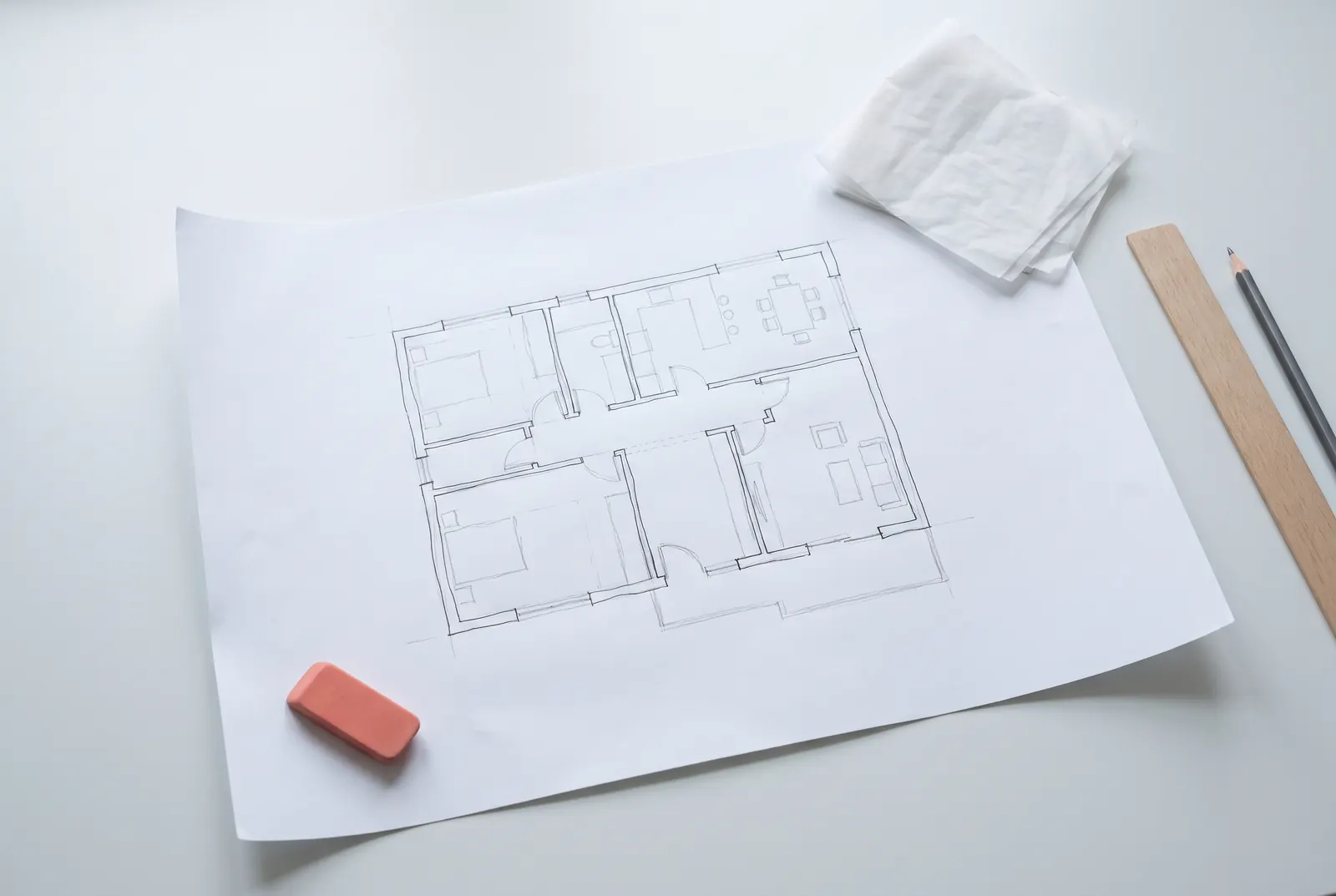
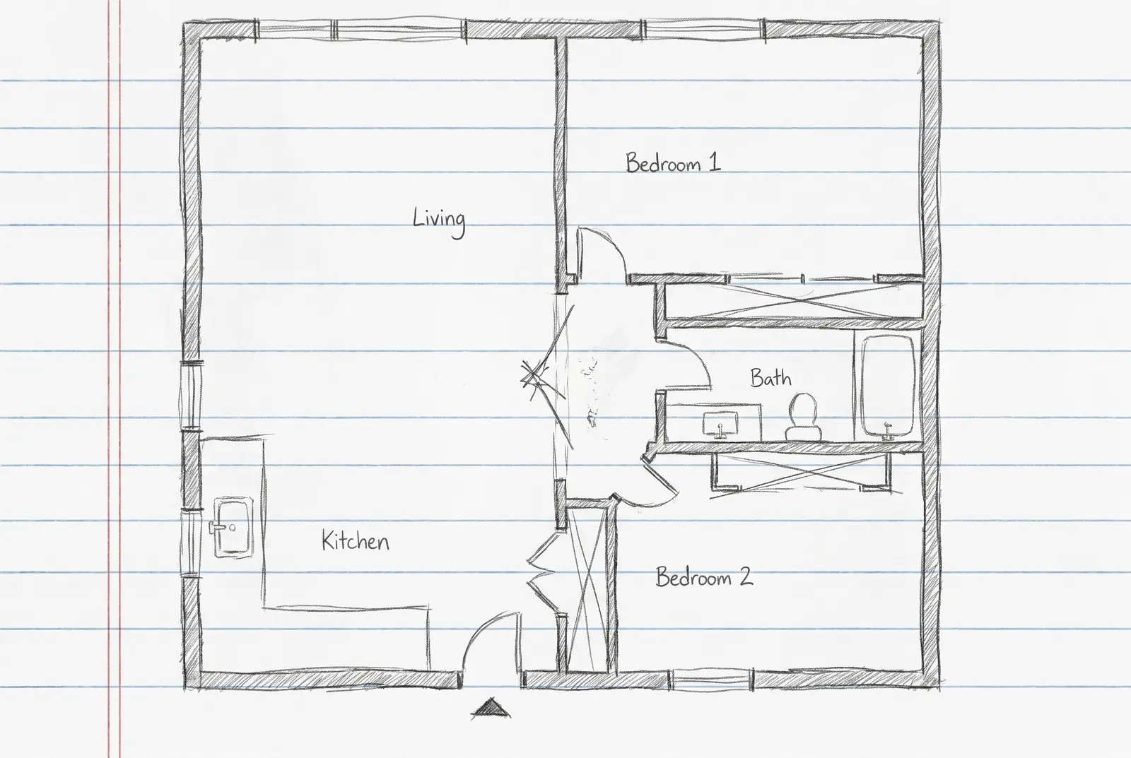
If what you have is a photo, a PDF or a hand sketch, rebuilding it at scale in the floor plan creator is the fastest way to see whether the symbols add up: doors that cannot open, a window landing behind a wardrobe, a beam over the only place for a bed. The companion post on how to read a floor plan covers line weight, scale and the five things clients misread; this one is the vocabulary that post assumes.
Draw it, then read it back
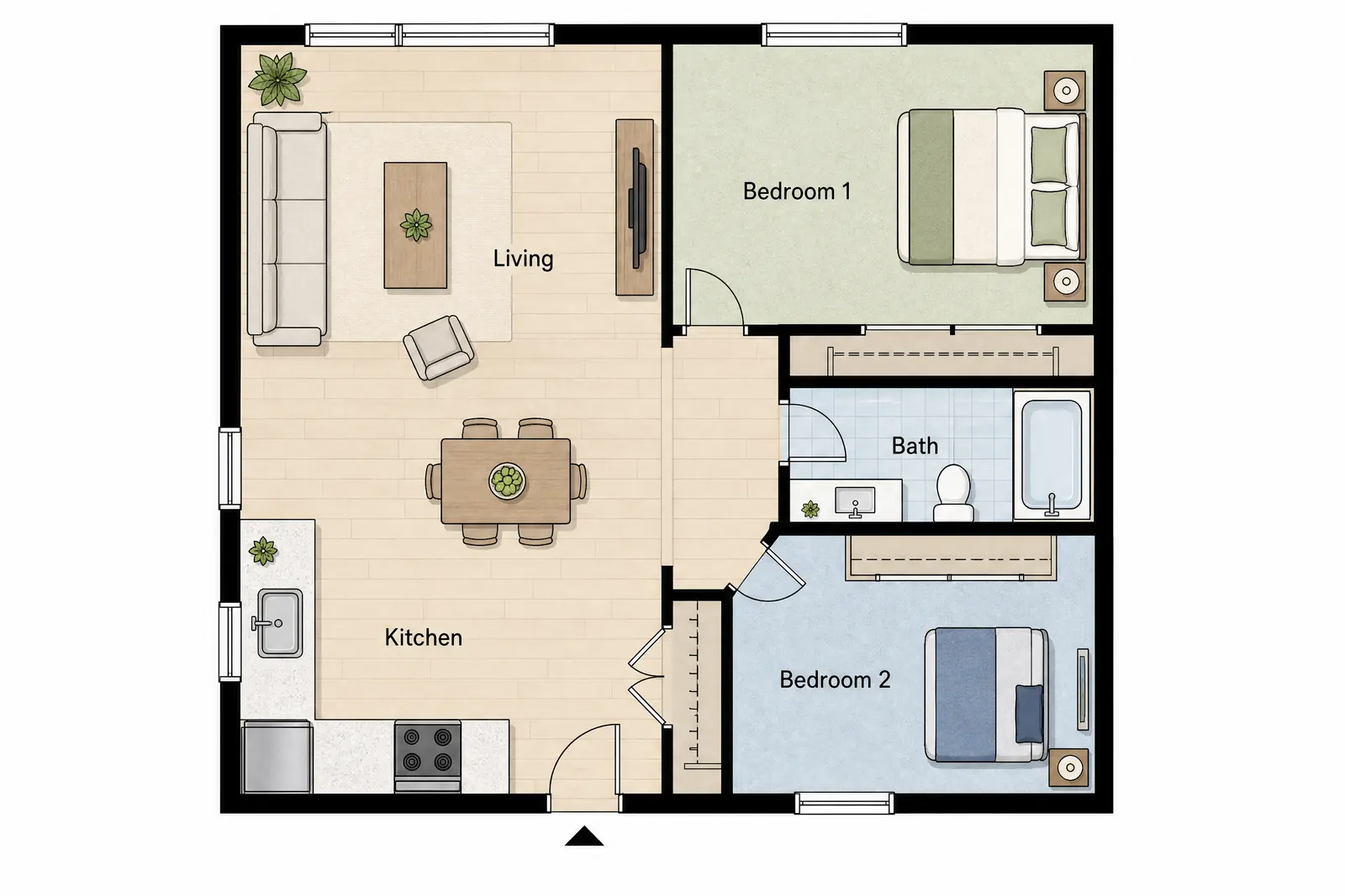
The generator draws doors, windows, stairs and fixtures as recognisable symbols at real size, so the plan can be checked before anyone prices it — and a pocket door swapped for a hinged one where the swing does not fit.
常见问题
What does DW mean on a floor plan?
Dishwasher, on a residential kitchen plan[3, 5]. It is not universal: one university facilities standard uses DW for distilled water[4], which is why the abbreviation list on the sheet wins over any chart[3].
Can I tell a load-bearing wall from the symbol?
No. A heavy or filled wall line shows that the wall is cut or emphasised, not that it carries load; bearing is settled on the structural drawings and by wall tags[3]. Treat any wall you plan to open as structural until someone qualified says otherwise.
Why does the same symbol look different in two drawings?
Architectural symbols are conventions rather than one fixed alphabet[3]. A national CAD standard publishes a symbol library and drafting conventions, but not every office or project uses it[3], and imported blocks can carry older linework or different parameters[3]. Read the legend first, then the tag[3].
来源
正文方括号里的数字对应以下来源。
- 1.Skills/Compétences Canada, SCNC 2019 – Drawing Standards, 52 – Architectural Technology & Design (Secondary), Appendix 1: Industry Drafting Standards, 访问于 2026年11月3日.
- 2.BOMA Oakland/East Bay, Reading Construction Plans – Property Manager Training (module 03: common floor plan symbols), 访问于 2026年11月3日.
- 3.ArchitectureCourses.org, Architectural Drawing Symbols: Complete Guide for Students and Professionals, 访问于 2026年11月3日.
- 4.University of Wisconsin–Madison Physical Plant, Symbols & Abbreviations (facilities CAD standard), 访问于 2026年11月3日.
- 5.City of Austin, Building permit plan set, abbreviations sheet (Austin, TX), 访问于 2026年11月3日.
- 6.RMIT University Learning Lab, Symbols – architectural drawings (electrotechnology toolbox), 访问于 2026年11月3日.